FAQ
The length of the cable depends on the pixel clock on the camera.
Please refer the following table, and note that the it may vary depending on cable’s specification and used environment.
| Pixel clock of camera | Available cable lengths |
| 85MHz | up to 1m |
| 80MHz | up to 3m |
| 66MHz | upt to 3m |
| 50MHz | up to 5m |
| 40MHz | up to 7m |
| 20MHz | up to 10m |
What is PoCL-Lite, and is there a board that supports this specification?PoCL Lite is a specification that limits the output bit to Mono 8, 10 bits, leaving a power supply function (PoCL) through a camera link cable.Smaller cable diameters increase flexibility, and the ability to miniaturize camera link connectors has the advantage of making the camera even smaller.
Models that support PoCL Lite have APX-3324A, support PoCL Lite from firmware version 1.8 or higher, and can connect up to four.
- APX-3302, APX-3324A
In case of Base Configuration, Up to 4W is supplied to the camera. - APX-3323, APX-3326A
In case of Base Configuration, Up to 4W is supplied to the camera.In case of Medium/Full/Deca configuration, up to 8W is supplied to the camera with the condition described below. (NOTE : The boards can supply up to 4 watts of power per CL connector as of PoCL standards.)
Therefore, if you are using a camera exceeding 4 watts of power consumption with Medium or Full or Deca Configuration, you should check if the power is supplied with 2 connectors (Base and Medium/Full/Deca)
Supplying more than 4 watts of power from the connecor may cause failure**.**
Connecting is possible, but if using a normal camera, power the camera before powering the PC.
This can cause camera damage or PC instability.
※ If you are using a camera that does not support PoCL, it is recommended to disable the PoCL function.
For CL Frame Grabbers that support multi-channel, you can connect the PoCL camera and the regular camera to the board together.
Instead, the channel that connects the PoCL camera must change the jumper settings on the board. For jumper settings, see the question “[PoCL camera] Do I need any settings when using PoCL?”.
- When windows starts, the PoCL camera automatically powers up. If you detach the camera link cable while running Windows, it will not power on automatically.
To turn the power back on, user can choose one of the followings .
- Use the AcapSetInfo function.
AcapSetInfo (hDevice, CAM_CH, ACL_POWER_SUPPLY, 3000, 1);
- Via AIP Tool
Find the PoCL botton on top menu bar, and click it to power up via PoCL
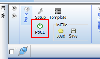
- Use the AcapSetInfo function.
- APX-3302
The jumper setting in the shipped state is ON and no separate setting is required if you are using a PoCL camera.The jumper position is located on CN7/CN8 below and the CN7 is Cam1 and CN8 is Cam2.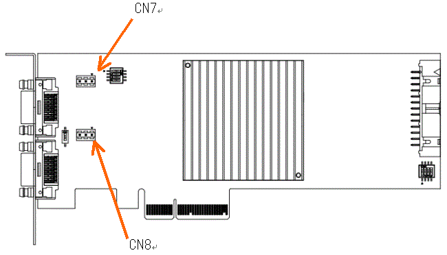

ON : For PoCL cameras, the board supplies power.
OFF : The PoCL function is not available.
- APX-3323
The jumper setting in the shipped state is ON and no separate setting is required if you are using a PoCL camera.The jumper location is CN7 below.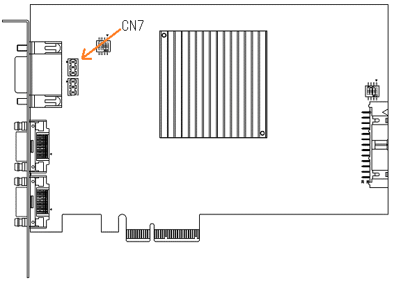

ON : For PoCL cameras, the board supplies power.
OFF : The PoCL function is not available.
- APX-3324A
The jumper setting in the shipped state is ON and may require a separate setting if you are using a PoCL camera.The jumper location is located at CN11/CN12/CN13/CN14/CN15 below, and CN11 is Cam1, CN12 is Cam2, CN13 is Cam3, CN14 is Cam4, CN15 is the setting for the PoCL power supply.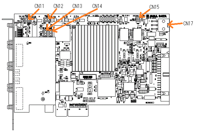

ON : For PoCL cameras, the board supplies power.
OFF : The PoCL function is not available.

EXT Con : The CN17 supplies power.
PCIE Edge : Power from PCI Express card edge.
Please refer to the table below for camera connection and jumper settings.
Connection status CN15 CN11~14 PoCL camera(1 camera) EXT Con or PCIE Edge Turn on ch to which the PoCL camera is connected Mix of regular and PoCL camera (one PoCL camera) EXT Con or PCIE Edge Turns on the ch to which the PoCL camera is connected, and turns off the ch to which the normal camera is connected. Mix of regular and PoCL cameras (two to four PoCL cameras) EXT Con Turns on the ch to which the PoCL camera is connected, and turns off the ch to which the normal camera is connected. Connecting only regular cameras EXT Con (Power supply exclusion) Turn off ch to which the normal camera is connected - APX-3326A
The jumper setting in the shipped state is ON and may require a separate setting if you are using a PoCL camera.The jumper location is located at CN11/CN12/CN13/CN14/CN15 below, and CN11 is the Base of Cam1, CN12 is the Full of Cam1, CN13 is the Base of Cam2, CN14 is the Full of CAM2, and CN15 is the setting for the PoCL power supply.

ON : For PoCL cameras, the board supplies power.
OFF : The PoCL function is not available.

EXT Con : The CN17 supplies power
PCIE Edge : Power from PCI Express card edge.
Please refer to the table below for camera connection and jumper settings.
Connection status Connection status 1 CN15 CN11~14 Numbers of PoCL camera Numbers of normal camera CN15 CN11~14 0 1 EXT Con(Power Supply Exclusion) 모든 ch을 OFF 0 2 EXT Con(Power Supply Exclusion) 모든 ch을 OFF 1 0 EXT Con or PCIE Edge Turns on the ch for connecting the PoCL camera and turns off the ch for connecting the normal camera. 2 0 EXT Con Turn on every ch 1 1 EXT Con or PCIE Edge PoCL 카메라Turns on the ch for connecting the PoCL camera and turns off the ch for connecting the normal camera.
When selecting a PC to use Frame Grabber, PCI-Express spec check is highly recommended.
If this specification does not meet the system bus specification of the Frame Grabber, the problem can occur, for example, the frame grabber is not recognized or 100% performance is not performed.
Please check the specification of System BUS (typically PCIE) on the board and select a PC with a slot that meets the requirements.
※ For your information, if the board is installed in the PCI Express x16 slot exclusively for graphics cards, it may not work properly, so please select a PC that has more than the required number of slots except that slot.
If you connect the frame grabber to x16 port designed for a graphic card, it may not work properly.
To maximize the performance of the graphics card, the main board manufacturer may have it assigned to graphics card usage only, and it is not clear.
So, the slot for the graphics card-only is not highly recommended to use with the frame grabber.
- APX-3302, APX-3323, APX-3324A, APX-3326AThe input frequency of the encoder can be entered up to 1MHz.
- APX-3302, APX-3323, APX-3324A, APX-3326A
If an external buffer is registered in the AcapSetBufferAddress function, the ACL_REVERSE_DMA at registration is reflected.
Therefore, to set the software, please follow these steps below.※ Skip error handling.
// Use ReverseDMA
AcapSetInfo (hdev, nCH, ACL_REVERSE_DMA, -1, 1);// Register buffer
AcapSetBufferAddress (hdev, nCH, ACL_IMAGE_PTR, -1, pbuf);// Apply settings
AcapReflectParam (hdev, nCH);
- APX-3302, APX-3323, APX-3324A, APX-3326A
Check if the model is correspond to following two cases, and then set them for each case
- The CC signal may be disabled and the strobe signal may not be output.
- The strobe signal may not output because the pulse width of the strobe signal is set to 0.
※In case of 1 or 2 please set the software as below. If there is no such item, please press here
1. activate CC signal
// Validize CC signal
AcapSetInfo (hDev, nCh, ACL_EXP_EN, -1, 1);
// Apply settings
AcapReflectParam (hDev, nCh);
2. set the pulse width of the strobe signal
// Set the pulse width of the strobe signal to 5 us
AcapSetInfo (hDev, nCh, ACL_STROBE_TIME, -1, 5);
// Apply settings
AcapReflectParam (hDev, nCh);
- APX-3302, APX-3323, APX-3324A, APX-3326A
Please use within the following range.
· H level : Between 2.4V and 5.0V
· L level : Between 0.0V and 0.8V
※ Do not apply more than 5.0V to the TTL terminal.
- APX-3302 series, APX-3323 series, APX-3324A, APX-3326AYou can connect an encoder of the line driver output type.
Encoder of complimentary output type or NPN output type is not available.
- Based on the use of APX-3312, APX-3313, APX-3318, APX-3302, APX-3323, APX-3324A, APX-3326A,
Under Software, perform the following settings. (※ Skip error handling)
// activate external trigger
AcapSetInfo (hDev, nCh, ACL_EXT_EN, -1, 1);
// CC 1 Shot output mode with 1 external trigger
AcapSetInfo (hDev, nCh, ACL_EXT_MODE -1 0);
// use encoder (actually do not need to connect encoder)
AcapSetInfo (hDev, nCh, ACL_ENC_EN, -1, 1);
// use external trigger as matching pulse in encoder
AcapSetInfo (hDev, nCh , ACL_ENC_START, -1, 2);
// apply settings
AcapReflectParam (hDev, nCh);
Chatter time is the time that an external trigger can hold the waveform.
Since the external trigger operates in a falling edge, the point at which the trigger pulse transitions from high to low , holding high and holding low must remain at least the set Chatter time. If each state is maintained for a time set to Chatter Time, it is recognized as an external trigger.
Setting Delay time allows you to recognize the trigger signal after it is recognized as an external trigger in the above state and is delayed by the set Delay time.
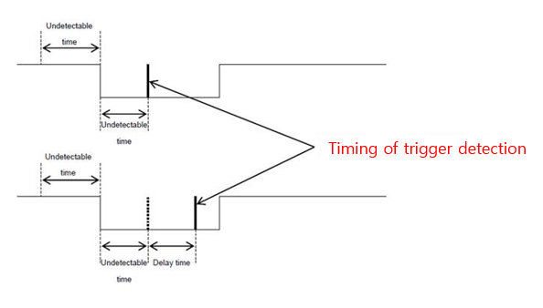
In addition, if an external signal, such as noise, is detected during the low state of the trigger pulse, it remains low as Chatter Time, and then it is recognized as a trig.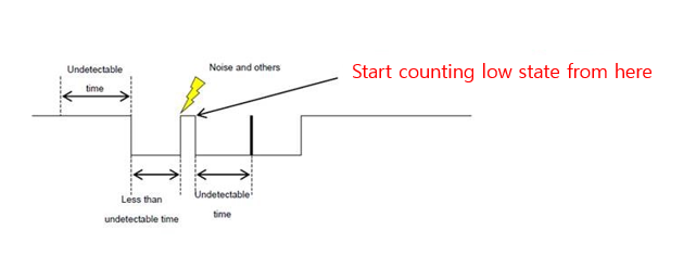
Unable to select.
The detection edge is only available with the Falling Edge.
It is trigger signal generated by external source and input to the frame grabber normally.
External triggers are mainly used to control the start of image acquisition or encoder operation.
※Please be careful to use when using TTL signal because operation may be affected by noise easily.
GPOUT has three functions.
- APX-3324A, APX-3326A, APX-3323
- Strove output Outputs a strobe signal. You can use GPOUT as the strobe output by setting the
AcapSetStrobfunctionACL_STROBE_ENto “Use strobe output”. With this setting, capture plugs and general output are not available. - Print capture flag Available when storbe output is invalid. Set
ACL_GPOUT_SELto0. The capture flag is a signal that is low during image input and high during stop. When entering the image, internally Y-sized calculations are displayed and refers to the signal below.
— Input start —
- Universal output Available when strobe output is invalid. Set
ACL_GPOUT_SELto1. Randomly determine the signal status ofACL_GPOUT_POL.Lowcondition whenACL_GPOUT_POLis0,Highcondition whenACL_GPOUT_POLis1.
- Strove output Outputs a strobe signal. You can use GPOUT as the strobe output by setting the
- APX-3324A, APX-3326A 8 signal pins dedicated to universal output and 4 signal pins dedicated to stroke are implemented are inplemented individually. (APX-3326A has 2 stroke-only pins.) Refer
ACL_GPOUT_POLin the SDK-AcapLib2 Library Manual for control methods. ⇒ Manual Download Page link
Each board has slightly different specifications for the extended connector, each of which can be found in the manual. Please ask the local cable maker to make it according to your specifications or contact our sales representative.
- APX-3302, APX-3323, APX-3324A, APX-3326A
Cannot arrange more than 8k pixels per tap.
- APX-3302, APX-3324A
Supports output patterns of 2TAP, 3TAP. You can also change the output direction for each tap. (horizontal size 1536)
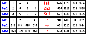
(after sorting process)

- APX-3318, APX-3323, APX-3326A
Tap output method Tap outpu direction is set randomly. For more information, see “Alignment Information Structure” in “AvalCapture Library2 LibraryManual”.
We have completed the test on our website. You can find the makers at the link below.
In addition, for the CameraLink board, the ini file, which is the camera setup file used by the SDK, can be found at the path below. If you can’t find the file of the camera model you’re using, please contact our technical support team.
Installation folder – [AVALDATA] – [SDK-AcapLib2] – [Sample] – [IniFile]
If the board is not recognized, make sure that the following points are not relevant.
- Check if mainboard BIOS is the latest version. Download and install the latest version of BIOS from the manufacturer’s website. (※ There are cases where the board was not recognized by the mainboard below, but was resolved after updating the BIOS to the latest version.
-Richo : FB15 -Gigabyte : GA-EX58-UD5, GA-EX58-UD3R - Update the chip set (graphic card) driver to the latest version.
- Update drivers for that board to the latest version Contains drivers for bards in SDK
- Check if 3G option is present.
- Install and run programs with administrator authority.
- Check if board is recognized by mounting in another PCI Express slot.
- Check if your PC recognizes the board when you replace it with another board.
- Check that the Plug & Play item is set to ON in the BIOS settings
- If you are using a separate graphics card in your PC, disconnect the graphics card and see if the board is recognized.
- Check if you are using a PC with Intel® Xeon® Processor E5 v2 Product Family or higher (in this case, upgrade the firmware on the board to the latest version.)
- Check that the Detect Non-Compliance Device item is disabled in the BIOS settings.
Payload means the data transmitted in use, and typically the payload when using Frame Grabber means the packet size of the data sent and received via PCI Express. Large payloads increase the amount of data transmitted per hour, and the maximum value of the payload depends on your PC(chip set). Also, since the amount of data that can be transmitted depends on payload (although it depends on the camera specifications), 256Kbyte payload may be required to receive the Max. frame of the CL Full camera without data loss.
The Max. size of the payload can be found in the Device Manager.

Under [Aip] – [APX 3***(Image Capture Module), select “Properties” – “Status tab”.
Please check the value displayed in ” Maximum payload size”(within the red border below).
It means the abbreviation of Power Over CameraLink, and this stands for powering the camera with a camera link cable.
For cameras that support PoCL, the PoCL-only camera link cable is required, and no power supply is required through the power cable.
※ Caution : Use either PoCL or external power.
- CameraLink Camera
Camera settings are typically set using serial communications software provided by the camera manufacturer.
Virtual COM settings are required in advance for serial communication.
(Virtual COM Link required.)
- Size X (ACL_X_SIZE)
All boards have the following limitations.Model Name Tap and Bit Threshold APX-3312 1Tap 8~65528 (a multiple of 8) 2Tap 16~65520 (a multiple of 16) APX-3313 Total Tap 8~65528 (a multiple of 8) APX-3318 1Tap 8~8192 (a multiple of 8) 2Tap 16~16384 (a multiple of 8) 4Tap 32~32768 (a multiple of 8) 8Tap 64~65472 (a multiple of 8) 10Tap 80~65520 (a multiple of 80) APX-3311 1Tap 16~4096 (a multiple of 16) APX-3662 8bit 16~131056 (a multiple of 16) 8bit (HighClip or Bit Shift) 16~65520 (a multiple of 16) 10~16bit 8~65532 (a multiple of 8) RGB 8~32760 (a multiple of 8) APX-3302 APX-3324 8bit / 1tap 16~8192 (a multiple of 16) 8bit / 2tap 16~16384 (a multiple of 16) 8bit / 3tap 48~24576 (a multiple of 48) 10bit~16bit / 1tap 8~8192 (a multiple of 8) 10bit~12bit / 2tap 8~16384 (a multiple of 8) 24bitRGB / 1tap 16~8192 (a multiple of 16) 32bitRGB / 1tap 8~8192 (a multiple of 8) APX-3323 APX-3326A 8bit / 1tap 16~8192 (a multiple of 16) 8bit / 2tap 16~16384 (a multiple of 16) 8bit / 3tap 48~24576 (a multiple of 48) 8bit / 4tap 32~32768 (a multiple of 32) 8bit / 8tap 64~65536 (a multiple of 64) 8bit / 10tap 80~81920 (a multiple of 80) 10bit~16bit / 1tap 8~8192 (a multiple of 8) 10bit~12bit / 2tap 8~16384 (a multiple of 8) 10bit~12bit / 4tap 32~32768 (a multiple of 32) 10bit / 8tap 64~32768 (a multiple of 64) 24bitRGB / 1tap 16~8192 (a multiple of 16) 30bitRGB / 1tap 8~8192 (a multiple of 8) 32bitRGB / 1tap 8~8192 (a multiple of 8) 32bitRGB / 2tap 8~16384 (a multiple of 8) - Size Y(ACL_Y_SIZE)
User can set the value without a limitation of the multiples and can set it by unit of the line. However, the maximum Y size has limitation as shown, and it differs to the model.
Model Threshold APX-3312 1~16777215 APX-3313 1~16777215 APX-3318 1~65535 APX-3311 1~16777215 APX-3662 1~65535 APX-3302 1~16777215 APX-3323 1~16777215 APX-3324 1~16777215 APX-3326 1~16777215 For more information on size Y, please refer to the manual “
ACL_Y_SIZE in SDK-AcapLib2 Library Manual(J2OM080156 *).pdf”In the case the line camera is set to (ACL_Y_TOTAL=0), the camera keeps capturing until stop signal.
If this specification does not meet the system bus specification of the frame grabber,
you may encounter problems such as frame grabber is not recognized or not performing 100%.
Please check the specifications of System BUS (typically PCIE) on the board in the figure below and select a PC with slots that meet the specification.

※ Note that if a board is fitted to a PCI Express x16 slot exclusively for graphic cards, it may not work as expected,
so please select a PC that has more than the required number of slots except that slot.
If you connect a frame grabber to an x16 lane port specified as a graphic card on the main board of a typical PC, it might not work properly.
To maximize the performance of the graphic card, each main board manufacturer may have adjusted it for graphic card only,
and because its specifications are not clear, the graphic card-only slot is excluded from the frame grabber operation guarantee.
Please refer to the table below for each model specification.

- Hardware Bayer Conversion-enabled models using FPGA : APX-3302, APX-3323
For more information, please refer “SDK-AcapLib2 BayerConfig User ‘s Manual (OM13013 *). pdf”.
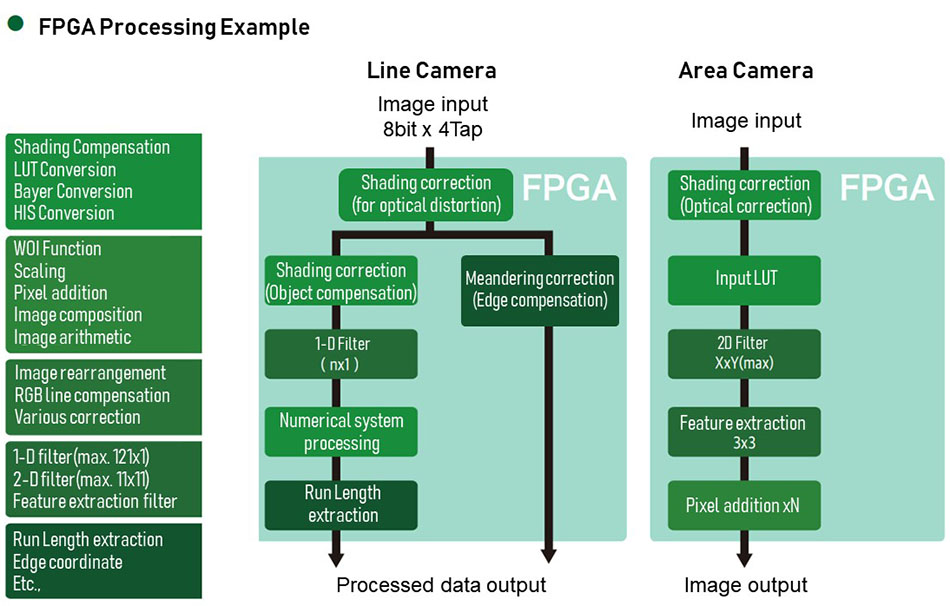
- A number of pre-processing functions can be implemented on the board using the board with FPGA(APX-3307, APX-3327-1-260). For more information, please refer the image below.
- APX-3302, APX-3324A, APX-3326A
You can connect. Even if the specifications of the copper clock, size, and output bit (black and white/color) differ, you can connect the cameras with different specifications, and you can connect the Area scan and Line scan cameras at the same time.
Yes you can. If you are using multiple boards, you need to set up each board ID for identification by the PC.
- Set as software switch
You can use the
firmwareUpdateTool.exeto set up a board ID.Please refer to
firmware update tool user guide (J3OM10026* ).pdffor instructions on how to set up. ⇒ 홈페이지에 포스팅 시, 매뉴얼 링크 걸기 - Set in the properties of each device
For APX-3302/APX-3323/APX-3324A/APX-3326A, you can set the board ID in the properties of the device. See below for instructions on how to set up.
- In Device Manager, right-click on “Aip→AVALDATA APX-xxx” and select properties.
- Specify certain numbers on board ID and click OK.
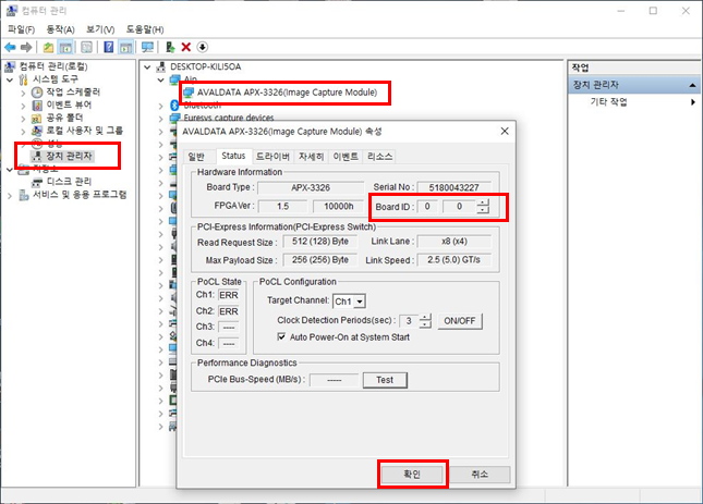
- Set by DIP switch on board
If you are using APX-3312/APX-3313/APX-3318, the DIP swithc on the boar can set the board ID from ‘0’ to ‘7’.
Please refet to the user manual of the product for how to position the dip switch.
This condition occurs when two or more boards are connected and the board’s ID is the same.
Please set a different board ID for each board.
If .NET Framework is not installed on your PC, error code 0x0000135 is displayed.
Install the .NET Framework (between versions 2.0 and 3.5).
The firmware on the board can be updated in the following order:
- Click the Start button and select the [AVALDATA SDK-AcapLib2] folder.

- Use the “Firmware Update Tool” located in the middle of the “Software” page that appears on the right side of the screen. See “SDK-AcapLib2 FirmwareUpdateTool Manual” for instruction on how to use it. (*)
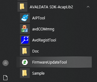
You can check the firmware version in the Device Manager.
Under [Aip] – [APX-3 *** (Image Capture Module), select “Properties” → “Status tab”.
The value displayed in “F/W Ver” (see below)
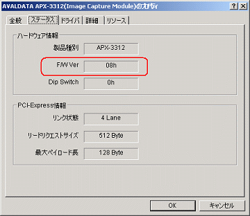
Occasionally, the Camera Setup Tool does not support COMport above COM10. If this occurs, you will need to check with the camera manufacturer.
Also, if you use Win32API’s CreateFile function to communicate, please refer to the Guide provided by Microsoft. See guidepage Link
Communication is possible, but the quality of the image data being output is not guaranteed.
If serial communication is required, it is recommended that you stop and execute image input.
clser***.dll is the file needed for the frame grabber and camera to communicate in series over the CameraLink interface.
A file named CLSerAva.dll is stored in the path below.
Installation folder – [AVALDATA] – [SDK-AcapLib2] – [CameraLinkSerial]
Virtual COM is a feature that allows Windows to assign and recognize the port that each camera in the Frame Grabber is connected to as a virtual COM port.
You can communicate with your camera on standard COM ports in Windows.
For the CL Full board(APX-3313, APX-3318, APX-3323, APX-3326), assign the BASE port as COM port.
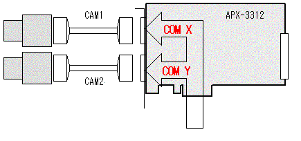
To use virtual COM, you must register a separate driver.
See “SDK-AcapLib2 VirtualComTool Manual (J2OM10016 *). pdf” for registration instruction.
“SDK-AcapLib2 VirtualCom Tool Manual” can be found at the following path after installing the SDK.
Installation folder – [AVALDATA] – [SDK-AcapLib2] – [doc]
If the settings on the camera and board do not match, the image cannot be acquired normally. Please check that the settings for the four items below are the same for both boards and cameras.
- image size (the number of valid pixel)
- output bit
- TAP
- shutter mode
In addition, a detailed description of similar probles and solutions can be found on the pages and videos of the website linked below (only Japanese is available now).
Web page : https://www.avaldata.co.jp/solution_imaging/cameralink_tips/aiptool_capture.html
You can store in bmp, csv, bin, jpeg, gif, tif, png format.
When you install SDK-AcapLib2, samples are stored in the path below.
Installation folder – [AVALDATA] – [SDK-AcapLib2] – [Sample]
If the status light on the board recognized by the AIP Tool is shown in red as shown below, then each state does not change.
You can update the latest status by clicking the refresh button. If the refresh button does not change the state, please check for problems with external triggers and encoder signals.
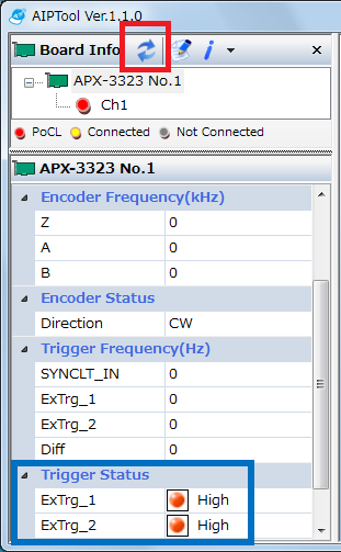
If you use a board that does not meet the AIPTool specification, the AcapLib2Viewer will start.
The following boards are supported.
· APX-3302 series
· APX-3323 series
· APX-3324A
· APX-3326A
If your PC does not have .Net Framework 4.0 or later installed, an error will occur. Please ensure that .Net Framework 4.0 or later is installed.
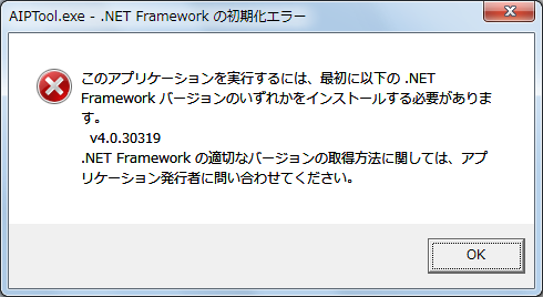
The AIP Tool is the latest viewer program and is compatible with the models
- APX-3302 series
- APX-3323 series
- APX-3324A
- APX-3326A
OS 64bit is not supported if SDK-AcapLib2 version is 6.1.0 or less.
Please use SDK-AcapLib2 version 6.1.0 or higher.
Sensors in a typcal bayer camera have R,G,B filters placed in a constant pattern, which is called a Bayer Pattern.
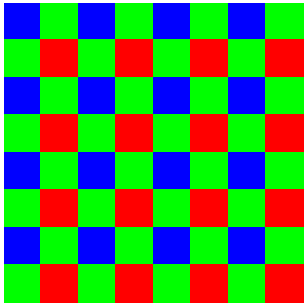
[Bayer Pattern]
The Raw data that is output without a Bayer conversion appears in the Bayer Patterns. Therefore, the image shows a check pattern or a different luminance value above and below. In addition, sometimes Go board patterns appear depending on the display scale.
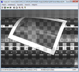
More information about the Bayer camera can be found on the linked page below.
The bayer camera outputs black and white image data called Raw data. To convert this data to color, a Bayer conversion work is required.
If you’re shooting with a bayer camera and the image is black and white, please check whether the Bayer conversion has been made.
More information about the Bayer camera can be found on the linked page below.
If the camera is operating in a free-run mode, the CC1 signal is ignored.
Therefore, set the camera’s setting to start the exposure mode when detecting Rising or Falling edge of CC1. (ex. trigger mode)
Please contact the camera manufacturer because the camera settings may vary from manufacturer to manufacturer.
Click here to find out more about how to set up the board for the camera connection.
If the camera is acting as a free-run, the Exposure time set on the board is not applied. To run with the Exposure time set on the board, please set the camera’s setting to Exposure Time Mode. The name of the Exposure Time Mode may vary from camera to camera, so please contact the camera manufacturer for information regarding camera setup.
Click here to find out more about how to set up the board for camera connection.
Exposure indicates the output width of the CC1 signal that the board outputs to the camera, and cycle indicates the output cycle.
You can change the output signal setting from CC2 to CC4.
For APX-3662, the exposure signal cannot be selected because it uses real-time triggers.
The relationship of the set values is as follows.


Make sure to set the Exposure < Cycle.
The camera with external synchronisation uses the CC1 signal as an exposure signal.
Check the operating mode of each camera for how the camera is operated by the CC! signal and adjust the Exposure, Cycle and Trigger mode(Falling edge/Rising edge) to match the setting.
For more information on CC signals, please refer to the linked page.
If the following pop-up window is displayed after the shoot, it means a timeout has occurred.

![]()
Timeouts occur when you execute the take command on the board but the take is not working properly. Timeouts may occur in the following cases:
- Camera’s output size < Board’s input size
→ Change the input size of the board by checking the camera’s output size.
- Timeout setup time is short.
→Set the timeout setting time to be longer than the 1 frame filming time.
- You have set it to an external trigger (TTL, RS22) but have not entered an external trigger.
→ Enter the external trigger or disable the setting.
- The camera is in exposure control mode, but no exposure signal has been output from the board.
→ On the board, set Cycle and Exposure to non-zero values.
→ Check the Exposure Polarity of the board.
- Encoder usage status is set, but encoder signal is not entered.
→ Enter encoder signal or disable encoder usage setting.
→ If you are setting up an external trigger fo the encoder, enter or disable the external trigger setting.
→ Make sure that the rotation direction(CW, CCW) of the encoder mathces the board settings.
The AcapLib2Viewer.exe can only set our boards and does not support the camera’s settings.
Virtual COM must be set up to replace what is related to serial communication.
You can store in bmp, jpeg, gif, tiff, png format.
Not included.
As we include a Console sample, please refer to the console sample source when creating the application.
The language of sample source code is VC++, VC#, and VB.NET.
The sample source code is stored in the path below.
Installation folder – [AVALDATA] – [SDK-AcapLib2] – [Sample]
Depending on the hardware specification, there is a size limit.
Therefore, you might not be able to film all the valid pixels of the camera.
※ For more information on X size, refer to “ACL_X_SIZE” in “SDK-AcapLib2 Library Manual (J2OM080156*) pdf”.
| Model Name | Tap and Bit | Range |
| APX-3312 | 1Tap | 8~65528 (a multiple of 8) |
| 2Tap | 16~65520 (a multiple of 16) | |
| APX-3313 | Total Tap | 8~65528 (a multiple of 8) |
| APX-3318 | 1Tap | 8~8192 (a multiple of 8) |
| 2Tap | 16~16384 (a multiple of 8) | |
| 4Tap | 32~32768 (a multiple of 8) | |
| 8Tap | 64~65472 (a multiple of 8) | |
| 10Tap | 80~65520 (a multiple of 80) | |
| APX-3311 | 1Tap | 16~4096 (a multiple of 16) |
| APX-3662 | 8bit | 16~131056 (a multiple of 16) |
| 8bit (HighClip or Bit Shift) | 16~65520 (a multiple of 16) | |
| 10~16bit | 8~65532 (a multiple of 8) | |
| RGB | 8~32760 (a multiple of 8) | |
| APX-3302 APX-3324 | 8bit / 1tap | 16~8192 (a multiple of 16) |
| 8bit / 2tap | 16~16384 (a multiple of 16) | |
| 8bit / 3tap | 48~24576 (a multiple of 48) | |
| 10bit~16bit / 1tap | 8~8192 (a multiple of 8) | |
| 10bit~12bit / 2tap | 8~16384 (a multiple of 8) | |
| 24bitRGB / 1tap | 16~8192 (a multiple of 16) | |
| 32bitRGB / 1tap | 8~8192 (a multiple of 8) | |
| APX-3323 APX-3326A | 8bit / 1tap | 16~8192 (a multiple of 16) |
| 8bit / 2tap | 16~16384 (a multiple of 16) | |
| 8bit / 3tap | 48~24576 (a multiple of 48) | |
| 8bit / 4tap | 32~32768 (a multiple of 32) | |
| 8bit / 8tap | 64~65536 (a multiple of 64) | |
| 8bit / 10tap | 80~81920 (a multiple of 80) | |
| 10bit~16bit / 1tap | 8~8192 (a multiple of 8) | |
| 10bit~12bit / 2tap | 8~16384 (a multiple of 8) | |
| 10bit~12bit / 4tap | 32~32768 (a multiple of 32) | |
| 10bit / 8tap | 64~32768 (a multiple of 64) | |
| 24bitRGB / 1tap | 16~8192 (a multiple of 16) | |
| 30bitRGB / 1tap | 8~8192 (a multiple of 8) | |
| 32bitRGB / 1tap | 8~8192 (a multiple of 8) | |
| 32bitRGB / 2tap | 8~16384 (a multiple of 8) |
Not available
We can provide the initial file by mailing you used on another board, or by giving you the model name of the camera you are connected to.
ini file is the setting file containing specific setting on its parameter. When you load the ini file, the settings are set to the certain values of the camera saved in ini file which is provided from the SDK. When editing the ini file’s settings, please be careful not to enter the value not allowed in system.
Quick Start is not supported. When using WIN10, please disable the Quick Start function.
Windows Store App is not supported.
If you revert to a previous version of AcapLib2 version 6.3.0, the above will occur, In this case, remove AVALDATA APX-3300 Windows SDK from Add/Remove Programs.
Not all OS’s sleep and hibernate modes are supported.
Possibly an area where the front buffer of the DMA registered is invalid.
Also, the leading address of the buffer needs to be in a 16Byte array.
In the following situations, the AcapSetBufferAddress function is an error and the AcapGetLastErrorCode function contains 0xF107(Initialization Failure).
- When the address of the buffer in front of the DMA is NULL.
- The size of the DMA buffer and the input size set in the ini file do not match.
- The processing bit setting and the size of the buffer in front of the DMA do not match.
<8bit > _aligned_malloc (x * y * sizeof (char), 16);
<10 · 12bit> _aligned_malloc (x * y * sizeof (short), 16);
<24 · 32bit> _aligned_malloc (x * y * sizeof (long) 16);
If you have not registered your license, each time you run SDK, a license registration pop-up window appears, as shown below. You can press OK to enter the SDK usage UI, and you can test all the features of SDK without having to enter a license key.(But, the corresponding pop-up will continue to pop up everytime you use it.)
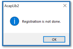
To remove the above pop-up window, you must purchase the SDK for the first time and register your license.
To register, please purchase the license and click the Windows button to register the purchased license by clicking AvdRegistTool in the AVALDATA SDK program folder as shown below.
(※Run registration as administrator.)

You only need to purchase the license once for user registration. No separate runtime license is required.
Development Language : C++, C#, VB.net
Development Environment : Visual Studion 2005 and Up
Other environment (such as Borland C++) are excluded from support.
Windows is responding to Japanese and English versions.
- Windows 7 | 32bit/64bit
- Windows 10 | 32bit/64bit
※If you are using AcapLib2 in Windows 10, be sure to check the link document.
There are restrictions on WOW64 operation.
- The current SDK does not respond.
- APX-3313
- APX-3312
- APX-3318
- Respond form SDK-AcapLi2 Ver6.7.0 and later.
- APX-3302
- APX-3323
- APX-3324
- APX-3326
Linux has a different package. Please refer to below.
- OpenSUSE13.1 | Linux Kernel 3.11.6-4 | 32bit / 64bit
- CentOS6.5 | Linux Kernel 2.6.32-431 | 32bit / 64bit
- APX-3302
- APX-3312
- APX-3323
- APX-3324
- APX-3326
- OpenSUSE11.0 | Linux Kernel 2.6.25.5-1.1 | 32bit / 64bit
- Fedora8 | Linux Kernel 2.6.23.1-42.fc8 | 32bit / 64bit
- APX-3313
- APX-3318
The two programs are incompatible with each other.
TransFlyer requires a new build because resources created by AcapLib2 are not available.
SDK-TransFlyer Migration Guide is provided for AcapLib2 users.
Please refer [TransFlyer Install Folder] – [Doc] – [TransFlyer_Programmers_MigrationGuide.pdf].
SDK-TransFlyer is a completely different software package than SDK-AcapLib2.
- SDK-TransFlyer is based on GenICam (According to EMVA, FA Industry Standard Camera Control Specification) and is an SDK used in GenICam-based products such as our CoaXPress, Gig.E.
- SDK-AcapLib2 is software developed by our company and SDK is required when using the CamearLink product.
The Standard Feature Naming Convention (SFNC) and GenTL are excellent, enabling connection, control, and image input to third-party SDKs and Libraries.
Causes can be the following factors.
- Cable connection problem : Make sure the cable is connected to the appropriate connector.
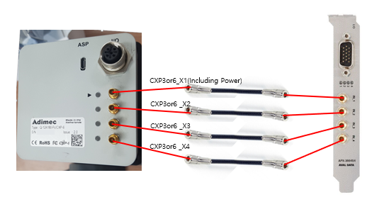
- Power supply : If the camera used does not support PoCXP, separate external power must be connected to the camera.
- Restart your PC and camera : Restart your PC and camera and then make sure they are connected.
Open Device Manager to see if your frame grabber is displayed, such as [Aip] – [AVALDATA APX – ****].

- If the board is not listed in Device Manager, please install the driver by model within the [Driver] folder on the installation media.※Note : If you are using our CXP model (APX-3664 series, APX-3662V2, APX-3661, APX-3636A, APX-3634, etc.) Please install the driver in the integrated driver
APX-3600folder.
- The board is displayed in Device Manager, but is not recognized when executing SDK.Open [Control Panel] – [Systems and Security] – [Systems] – [Advanced System Settings], and then open [Environment Variables] on the Advanced tab.
Then open GENICAM_GENTL*_ PATH in the system environment variable.
(GENTL32 in 32bitOS and GENTL64 in 64bitOS)
Verify that the variable value entry has a variable (The case of C drive, C:\AVALDATA\TransFlyer\bin\***) that represents TransFlyer.
If a third party other than TransFlyer has SDK installed, it may not be recognized properly.
In this case, you need to back up the original variable values, such as text files, and then remove any other variables than TransFlyer, and then reboot your PC to see if it improves.
Sensors in a typical bayer camera have R,G,B filters placed in a constant pattern, which is called a bayer pattern.

[Bayer pattern]
Raw data that is output without a Bayer conversion will show a Bayer pattern, which will then be converted to a color image if this data goes through a Bayer conversion.
Some cameras can self-Bayer conversion, but in most cases, you’ll need to do a Bayer conversion in Software.
Refer to the sample code included in the following location for how to do Bayer conversion by SW.
Sample code [Snap_Bayer] in [TransFlyer Install Folder] – [Examples]
You can also do Bayer conversion from TSight, and you can set it up by clicking Software on the Color tab.
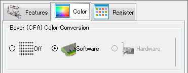
Movie recording is possible on TSight.
Please refer Recording Tab at the top of TSight.
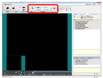

You can save it in avi format.
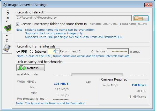
- CameraFor GenlCam Standart naming convention SFNC-compliant cameras, there is a feature called UserSetControl.
You can save and read settings using UserSet *.
- Frame GrabberYou can save and read settings using files in XMS format.
Caution: some setup items cannot be saved in an XMS file.
Check with IsStreamable.
SDK provides sample code for C++/C#/VB.NET. After installing the SDK, you can check the sample code at the following path.
[TransFlyer Install Folder] – [Examples]
There is a possibility that the camera and the frame grabber settings are inconsistent.
TSight is working to automatically set the settings between the camera and the frame grabber.
Please check if this processing is preceded by the applications you produce.
Please contact our technical support team (support@aval-global.com) or place of purchase. When inquiring, please send the explanation of the problem and the information below to confirm the problem faster.
- Information contained in the About TSight conversation that appears in [Help] – [Version] on the TSight
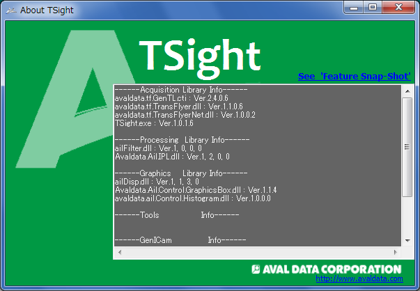
- When you run See ‘Feature Snap-Shot’ in the About TSight window, the following window appears. Save related information as a text file
※ You can obtain the current set value of the camera frame grabber.

All Feature is set to User Level, and no advanced items are displayed in the default settings.
Please change the settings of the User Level to set the User Level that displays the required items.
- Begginer : Displays only essential basic content.
- Expert : Displays more advanced functional items than the Beginner display.
- Professional : Display advanced settings for professional developers.
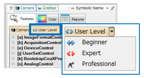
If the board is not properly connected to the camera, the parameter window will not be displayed.
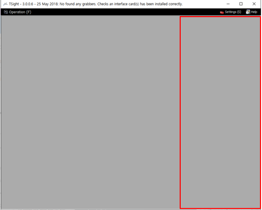
If it does not improve, reconnect the cable and restart TSight.
In TSight, a number of tasks such as initialization processing are performed in the background when running Snap, which requires a bit of time for Snap.
After VisualStudio 2010, development is possible at C++,C# and VB.NET.
Provides a sample project for VisualStudio 2010.
Available in the OS environment below.
Windows 7 32 / 64bit
Windows 10 32 / 64bit
The frame may be low due to the following reasons.
- PCIe BUS Speed The PCI Express slot does not meet the bandwidth required for image acquisition.
- Set camera link speed for CoaxPress response The link in the CXP might not be set to Quick Configuration. Make sure the link speed is set to the desired speed. GenICam standard naming convention SFNC compliant cameras can be set up in “CxpLinkConfigurationStatus”.
- Camera and frame grabber settings The camera and frame grabber have a variety of variables associated with the speed of the frame. It can change depending on the (frame speed, exposure time, capture mode, etc.) so make sure that the setting is correct forthe desired frame speed.
There may be several factors in the issue of image acquisition. Please check first to see if the following applies.
- The PCI Express slot does not meet the bandwidth required for image acquisition.
- In case of a hardware error in the frame grabber.In this case, you can see the current state of the frame grabber by flashing the panel LED. For more information, please refer [TransFlyer Install Folder] – [Doc] – [TransFlyer_UsersManual.pdf].
- If the cable is not properly connected or there is a problem with the cable. Confirmation is required, including cable length and connector connections.
- The camera is not powered. For cameras that do not support PoCXP, separate external power is required. For cameras that support PoCXP, make sure that the external power pin (6 pin) cable is connected to the frame grabber.
- The maximum payload is not large enough You can check the maximum payload size value in Device Manager. If the maximum payload size falls short of 256Byte, you may not be able to perform properly.
- A user-generated application experiences problems with image taking We need to check if the same problem occurs with our Viewer Program TSight. If there is no problem with TSight, the application is likely to have an error.
- If the above does not apply or if the action is taken in the above manner and the problem still occurs Please save the log in case of an error and contact our technical support team (support@aval-global.com) or place of purchase.
[How to save a log] To view the logs, open [TransFlyer Install Folder]-[Log]-[config]-[TransFlyer.ini] and annotate the currently active [ReportStyle=*], and use [ReportStyle=0]. Then compress LogTool.zip in [TransFlyer Install Folder]-[Bin][Win*****], and run LogTool.exe.
How to set up (To set up the Sync Control Specification by use, how to assign pins to I/O connectors, etc.) is being guided at [TransFlyer Install Folder] – [Doc] – [English]-[TransFlyer]-[WhitePaper]_[LinescanCamera_Encoder_ApplicationNote_e.pdf]. Please refer to the information in the manual, and if you have any questions during setup, please contact our technical support team.
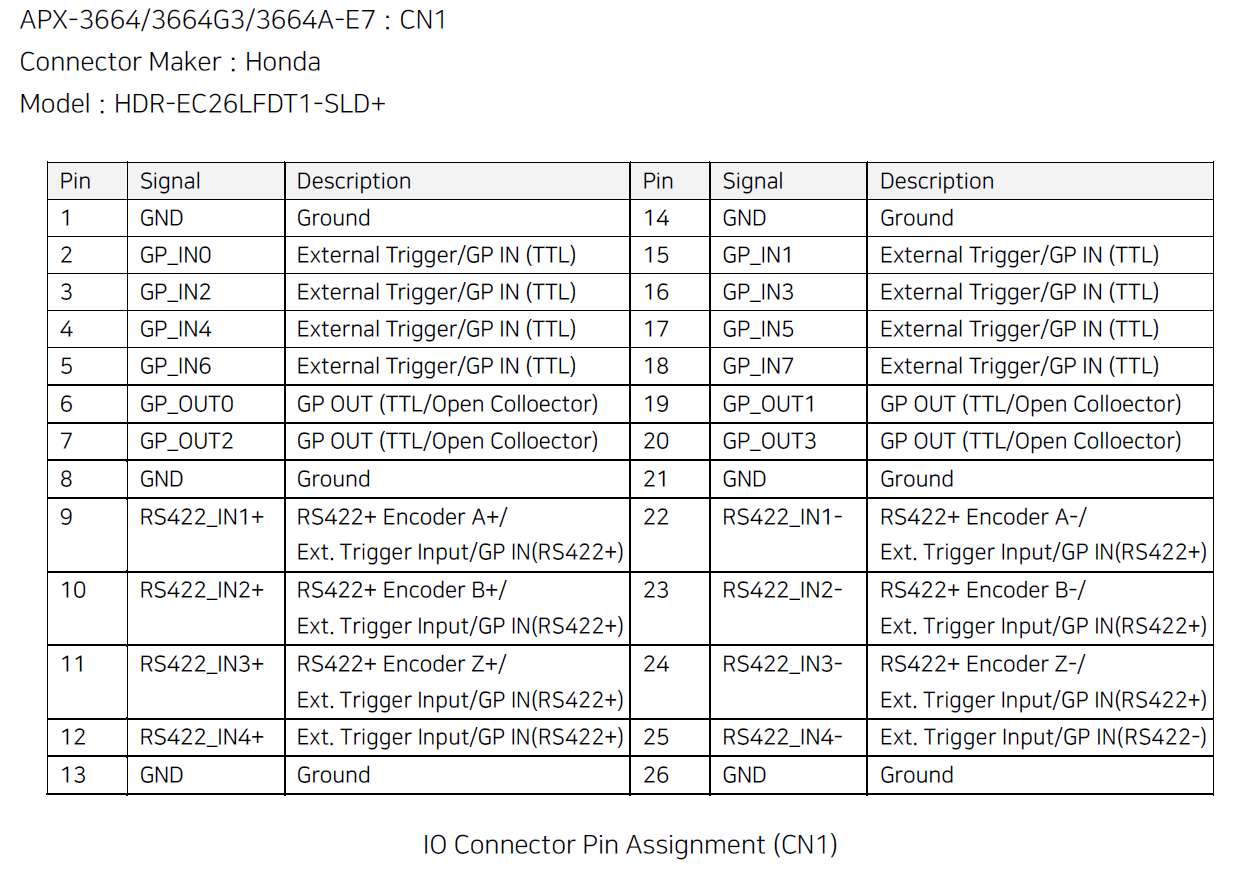
- APX-3664, APX-3664G3, APX-3664A-E7

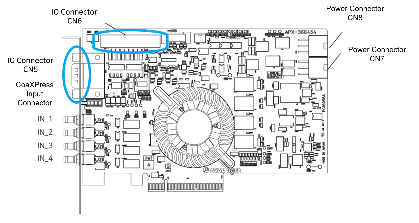
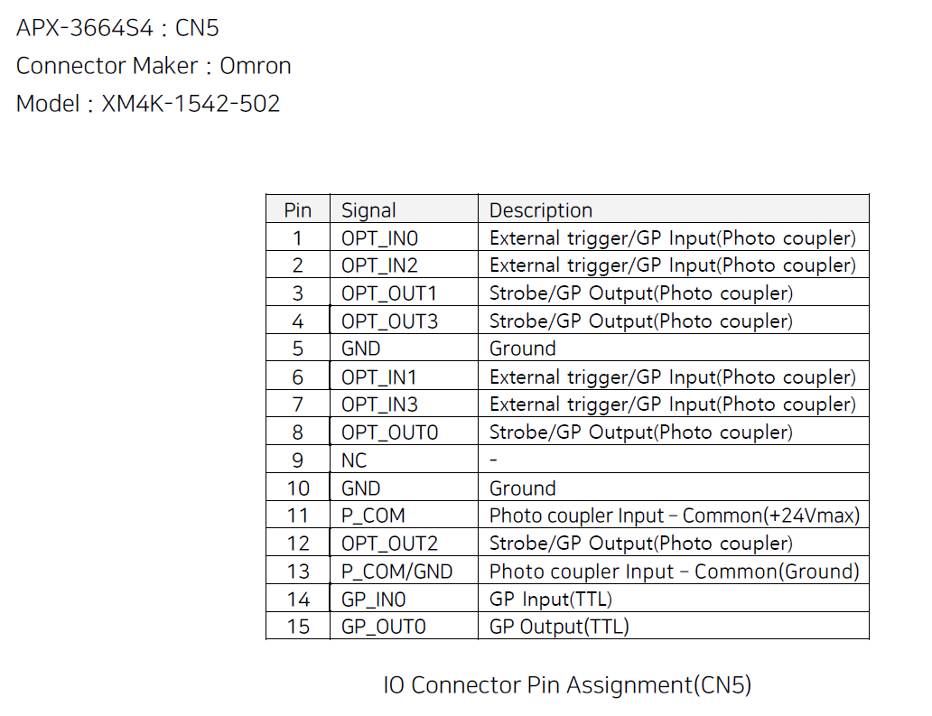
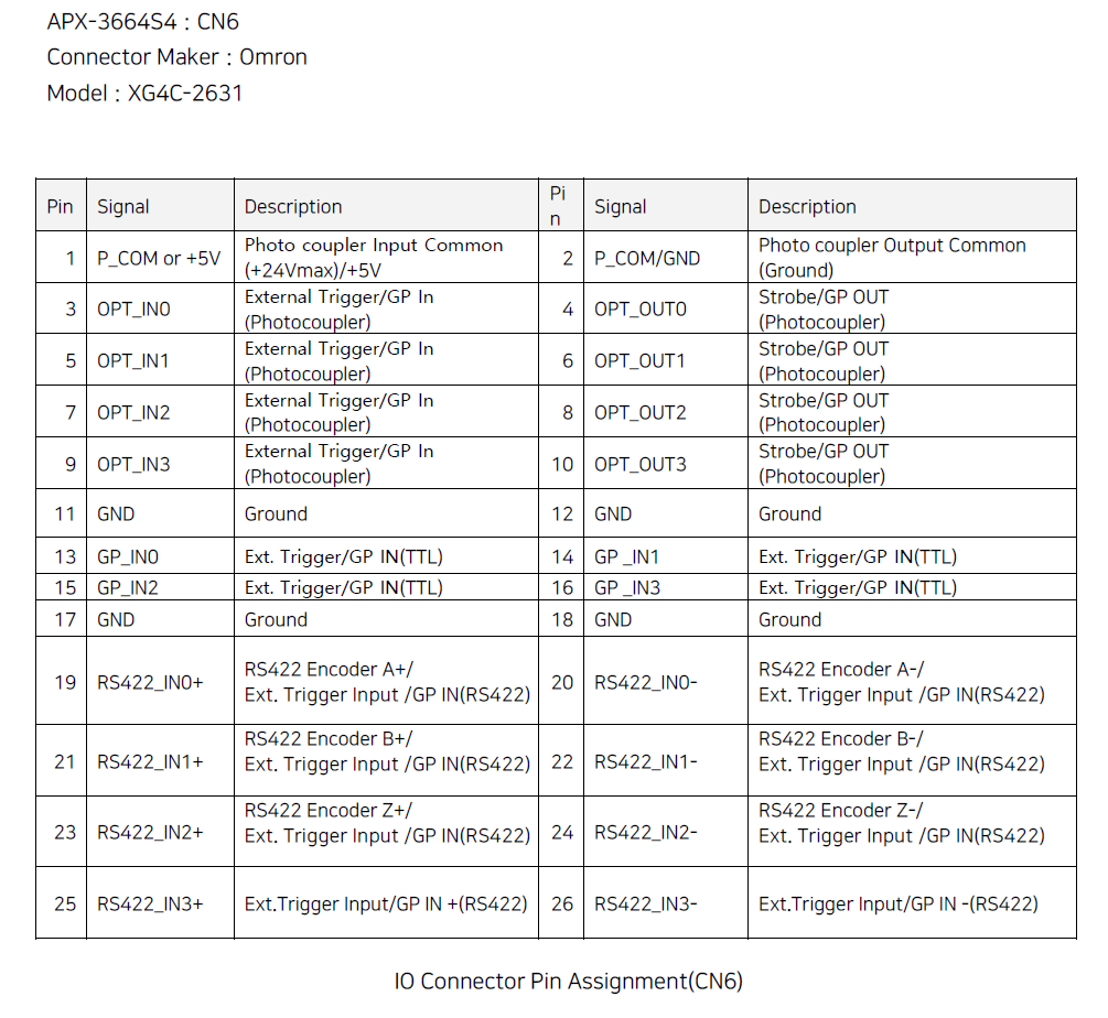
- APX-3664S4
- APX-3662V2
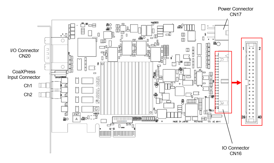
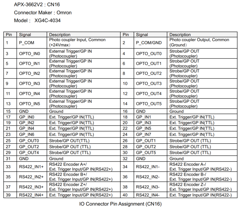
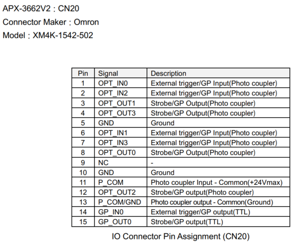
- APX-3661
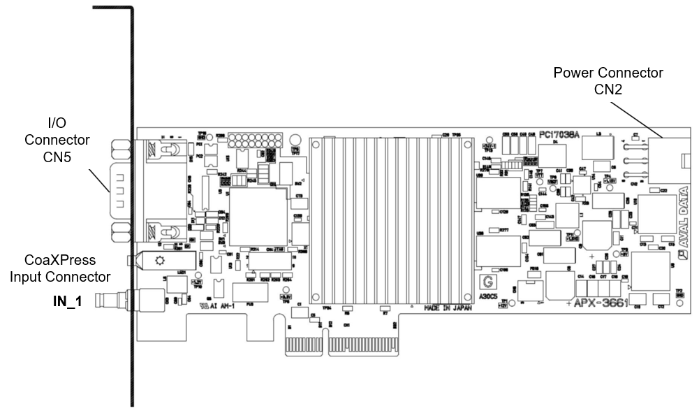
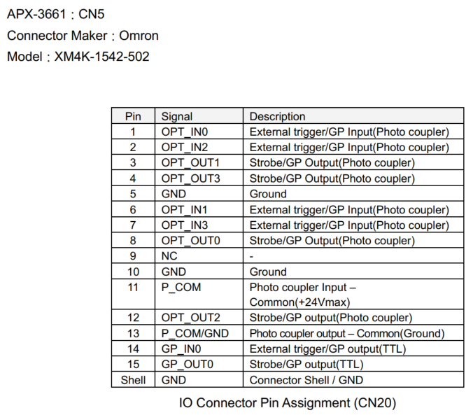
- APX-3636A
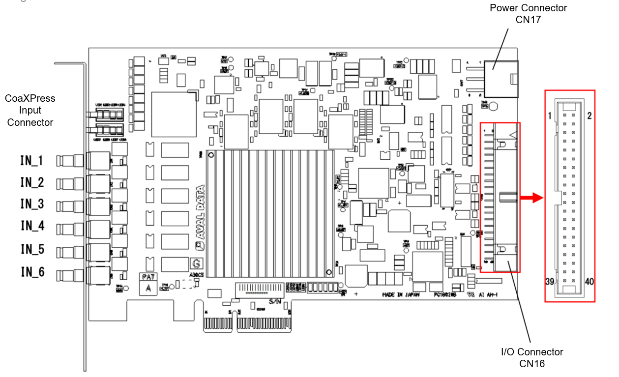
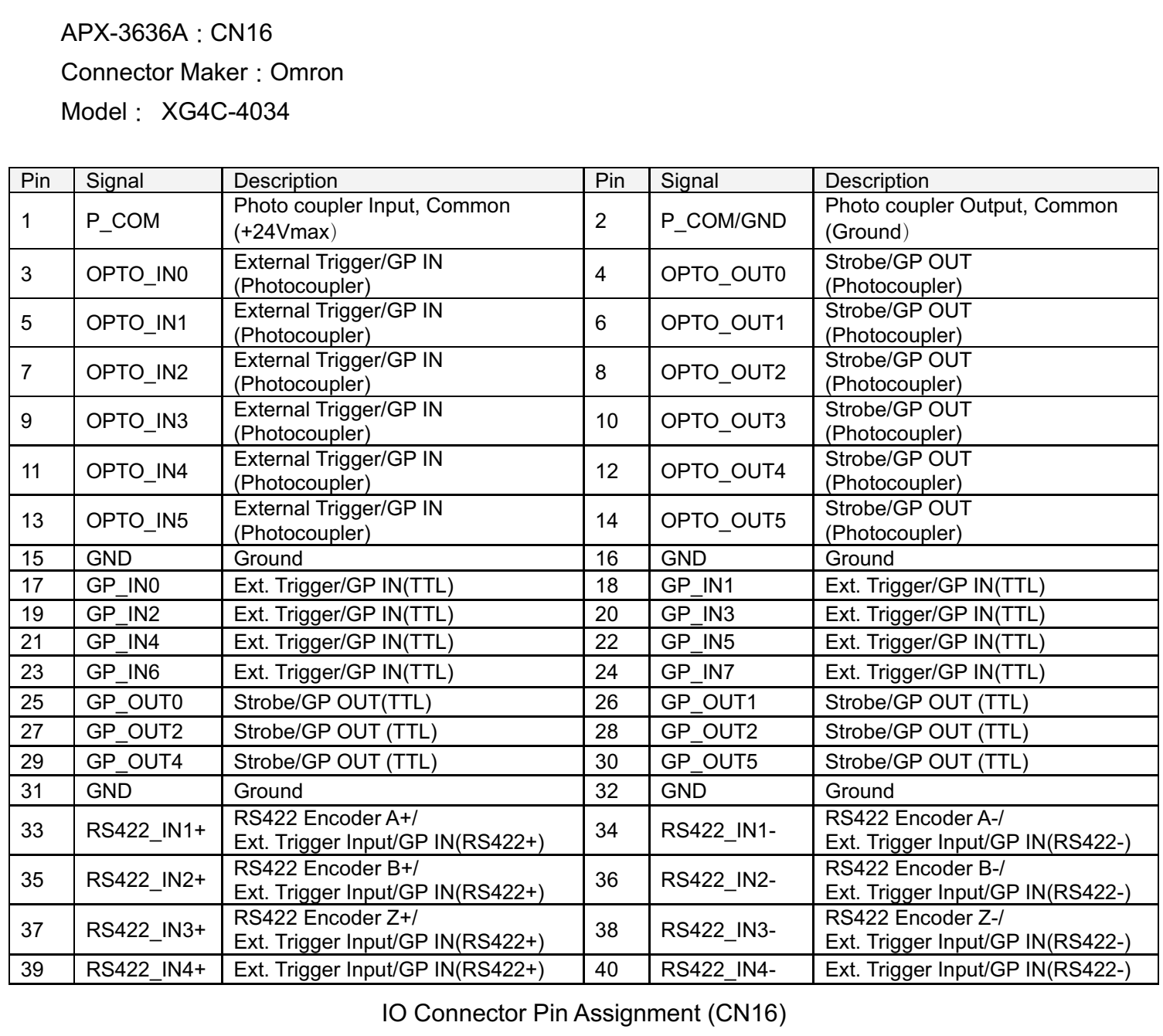
- APX-3634
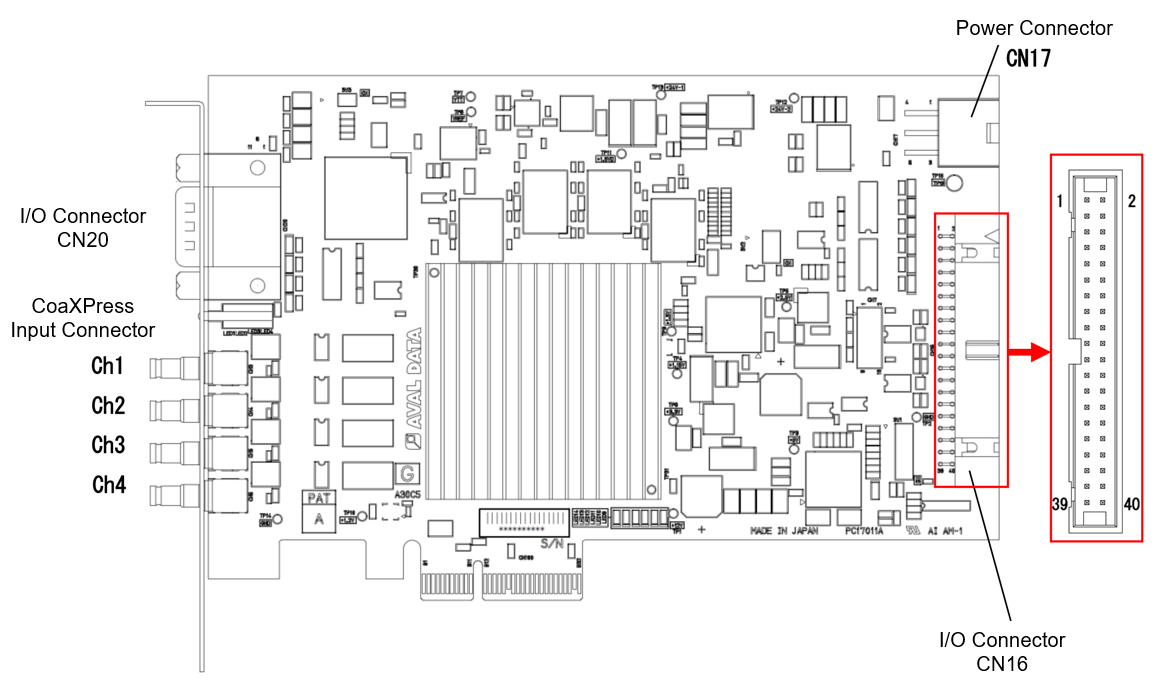
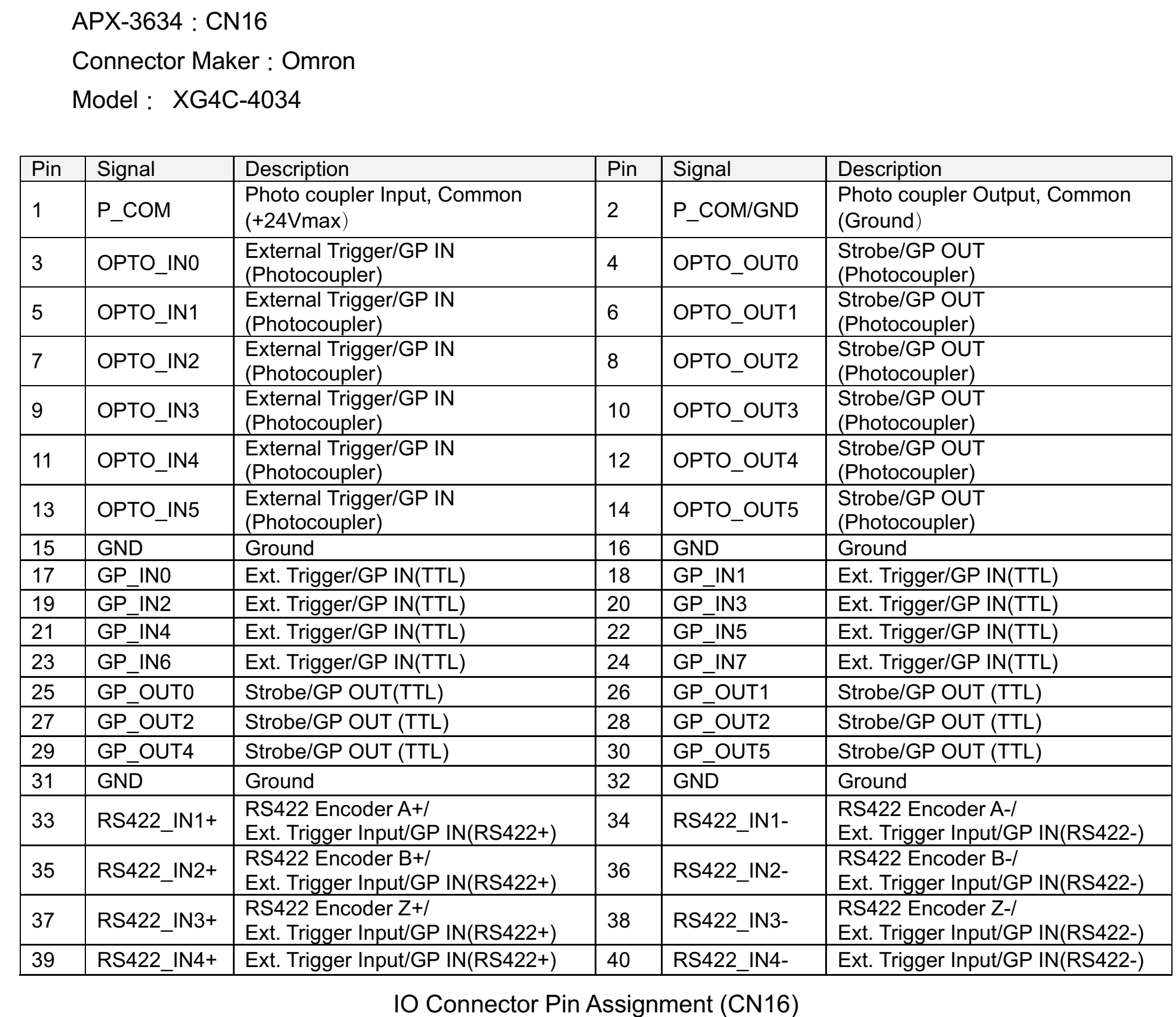
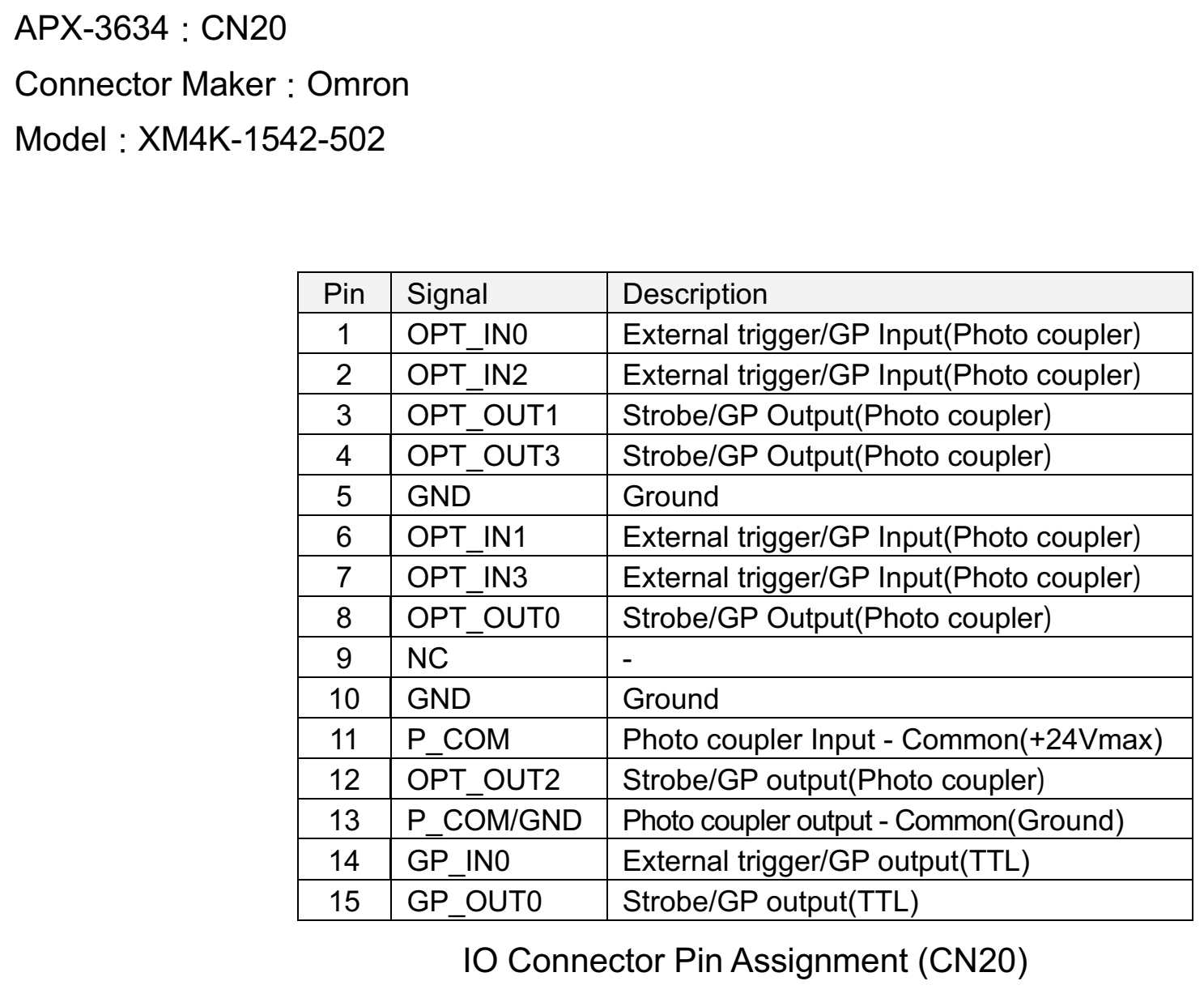
- APX-3664G3 : 1 for Quad, 2 for Dual / Single, up to CXP-6
- APX-3664S4 : 1 for Quad, 2 for Dual, 4 for Single, up to CXP-6
- APX-3664AE7 : 1 when connected by Quad / Dual / Single, up to CXP-6, (FPGA pre-treatmentable model)
- APX-3662V2 : 2 for Single connection, 1 for Dual connection, up to CXP-6
- APX-3661 : 1 unit when connected as Single, up to CXP-6
- APX-3636A : 6 units when connected to Single, up to CXP-3
- APX-3634 : 4 units when connected as Single, up to CXP-3
- Support for CXP-12 (12.5Gbps/Ch)
APX-36124
- Support for CXP-6 (6.25Gbps/Ch)
APX-3664G3, APX-3664S4, APX-3664AE7, APX-3662V2, APX-3661
- Support for CXP-3 (3.125Gbps/Ch)
APX-3636A, APX-3634
This happens when you enter an NTSC camera as a programmatically.
In ParameterID “Analog_ScanMode,” match the frame grabber scan mode.
For more information, see “Analog_ScanMode” in “ParameterID Reference .pdf” in [SDK-AcapLib+ Installation Folder] – [Doc].
Check that the Sync signal settings on the frame grabber and the camera match.
Select ParameterID as “Analog_Sync” whether to generate a frame grabber sync signal.
For more information, see “Analog_Sync” in “ParameterID Reference .pdf” in [SDK-AcapLib+ Installation Folder] – [Doc].
For frame grabbers for analog cameras, an error cannot be notified even if the image entry fails.
There is a possibility that the camera may not be properly powered or that the cable is not connected properly, etc.
Please check the above and see if you can acquire the images normally.
Sample code is provided for distributed processing.
Please refer “SampleOptCLinkDistribution” in [SDK-AcapLib+ Installation Folder] – [Sample].
Opt-C:Link → CameraLink converter has two models. Please refer to the below table.
| Property | AOC-162 | AOC-162MF |
| Number of connectable channels | 1 | 2 |
| UART baud rate | Variable | Variable |
| Base Config | O | O |
| Medium Config | X | O |
| Full Config | X | O |
| Deca 8bit/10bit | X | O |
| Switch camera trigger output | O | O |
| Availabe AcapLibPlus version | After 1.3.0 | After 1.3.0 |
There is a limit to the width that can be entered, please refer to the below.
| BitCount | Tap | AOC-162 | AOC-162MF | |
| 8 | 1 | 16384 | 16384 | |
| 10 | 1 | 8192 | 8192 | |
| 12 | 1 | 8192 | 8192 | |
| 14 | 1 | 8192 | 8192 | |
| 16 | 1 | 8192 | 8192 | |
| 8 | 2 | 16384 | 16384 | |
| 10 | 2 | 10922 | 10922 | |
| 12 | 2 | 10922 | 10922 | |
| 8 | 3 | 16384 | 16384 | |
| 24(RGB) | 1 | 5461 | 5461 | |
| 30(RGB) | 1 | X | 10922 | |
| 8 | 4 | X | 16384 | |
| 8 | 6 | X | 16384 | |
| 8 | 8 | X | 16384 | |
| 8 | 10 | X | 32768 | |
| 10 | 8 | X | 26214 | |
| 10-12 | 4 | X | 10922 | |
| 24 | 2 | X | 5461 | |
The following frame grabber models are available.
- APX-3800
- APX-3800X2
- APX-3841
Please click here to check further information of following models.

In case CameraLink camera users want to use Opt-C:Link (for long-distance transmission, noise resistance, etc.), they can configure the system using a converter (AOC-162) that converts CameraLink to Opt-C : Link.
Please click here to find out more about the converter.
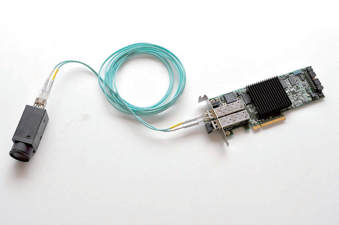
A unique interface developed by AVALDATA that enables image data transmission, trigger control, and serial communication between the camera and the frame grabber using optical fiber cables.
Because of optical communication, noise resistance is good and distance transmission is possible compared to other interfaces such as CameraLink and CoaXPress.
Communication speed can be up to 40Gbps.
A new interface that resolves the limitations of distance to transfer and noise-impacted environments that have been weak points for Camera Link, standard interface in machine vision.
Opt-C : Link is an interface with light as a medium. Bandwidth supports 40Gbps for QSFP+ optical module models and 6.25Gbps * 2ch for normal optical module models, with a connectionable distance of up to 150m for long distance data transmission. Image data, triggers, serial communications, etc. are all packetized and communicated over optical fiber cables.
Cannot be selected.
All our frame grabbers are only recognized by the Falling Edge.
Input to the appropriate pin on the extended connector of the frame grabber.
The type of extension connector, pin information, varies from frame grabber to frame grabber.
We also prepares an extension panel cable that is routed from the extension connector to the PCI standard panel.
For more information, please refer the respective frame grabber documentation in [SDK-AcapLib+ Installation folder] – [Doc] – [Hardware].
It is trigger signal generated by external source and input to the frame grabber normally.
External triggers are mainly used to control the start of image acquisition or encoder operation.
It is impossible.
Ver 1.4.0 currently, no model is capable of image processing by frame grabber hardware.
If the frame grabber is connected to more than one camera, cameras with different specifications can be connected.
It is possible.
You can distinguish by setting the ID number in the flash area of the frame grabber.
For settings, use the firmware update tool FirmwareUpdateTool from the following [SDK-AcapLib+ Installation folder] – [Tool].
※ The item Soft SW corresponds to the ID number.
If your PC does not have a .NET Framework 2.0″ or higher. NET Framework 3.5 or less, error code 0xC0000135 is displayed.
You can use the FirmwareUpdateTool.exe to update the firmware.
For more information, please refer the topic Setting up APX-3800 in “AcapLibPlus Installation Guide.pdf” in [SDK-AcapLib+ Installation Folder] – [Doc].
Please contact our sales department for confirmation of camera support.
LogTool program startup must have .NET Frameworks 4.0 or later installed. If you are using the lower version, please try the higher version and try again.
The camera setup tool may not support COM10 or later settings.
Please check with the camera manufacturer.
It is possible.
A feature for serial communication (COM port communication) with cameras connected to the frame grabber.
Windows recognizes each channel in our frame grabber as a virtual COM port and communicates with the camera with standard COM port control.
Virtual COM allocation is possible only for the Base connector of the Opt-C:Link and Camera Link frame grabber.
Opt-C:Link and Camera Link-response frame grabber is possible. To do serial communication, you must first use the virtual COM tool to complete virtual COM registration and setup.
For instructions on how to set up, please refer to the following documentation.
[SDK-AcapLib+ Installation folder] – [AcapLibPlus] – [Doc] “VirtualComTool Manual (J2OM10016D) .pdf”
You can convert to software using a library called AcapIPL.
We are providing sample code for processing the Bayer conversion, so please check the location below.
Please refer “IPLBayer ‘ and ‘CS_IPLBayer” in [SDK-AcapLib+ Installation Folder] – [Sample].
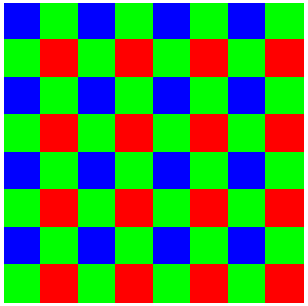
A Bayer color camera outputs black-and-white image data called raw data, and sensors in a typical Bayer camera have R,G,B filters placed in a constant pattern, which is called a Bayer pattern.
Bayer pattern
Raw data without a Bayer conversion will show a Bayer pattern, which will show a check pattern on the black-and-white image.
Bayer conversion processing is required to output this raw data as a color image.
Please enable the Bayer conversion feature in the setup section of the SDK.
More information about the Bayer camera can be found on the linked page below. (https://www.avaldata.co.jp/solution_imaging/cameralink_tips/aiptool_bayer.html)
The callback function is not included as the Basic AcapLib+ function.
EventCallbackClass.h provided with SDK defines API for callback function.
If you want to use callback, use it with the header above, and you can check the sample code for the callback function at the location below.
“EventCallbackClass” in [SDK-AcapLib+ Installation Folder] – [Sample]
Error occurs due to timeout. Please check out the followings.
- Check the size setting (Width, Height)
Make sure that the size settings are configured for the camera’s output size. (In some cases, the camera may cause the output to vary.)
- Confirm setting of trigger mode
The camera is set to output the image synchronously to the CC signal, but the frame grabber side may not output the CC signal or may not have the appropriate value.
An error occurs because an invalid parameter has been set.
Check the specification of the function and set the appropriate parameters because you might have set settings that the image input board or library does not support.
Camera may not connect correctly.
For camera links, please make sure that the connector is not connected correctly or that the camera is powered on (for PoCL, is powered on), etc.
In the case of Opt-C:Link, make sure status LED on the front panel is ON.
If LED goes in and out repeated, Link of the light cable is not normal.
Please refer to the “10. list of error numbers” in the user manual. The user manual can be found in the folder below.
[SDK-AcapLib+ Installation Folder] – [AcapLibPlus] – [Doc] – SDK-AcapLib + _UsersManual (OM14013) .pdf
If you can check the Japanese manual only, please contact your place of purchase or the technical support team of Aval Global.
The sample code is stored in [SDK-AcapLib+ Installation Folder] – [Sample].
- Basic Sample for working with SDK-AcapLib+
- SimpleSnap : Sample showing steps up to a simple capture (VC ++)
- SimpleSnap_MIL : Execuste snap and sending the image to memory of MIL (VC ++)
- SimpleSnap_SaperaLT : Execuste snap and sending the image to memory of SaperaLT (VC ++)
- EventCallbackClass : Sample codes for callback function (VC ++)
- OptCLinkDistribution : Samples about Opt-C:Link distribution of the image written from Master Node to the Slave Node (VC ++)
- AbsEncoderMultiPoint : Samples about how to use an Absolution encoder with (VC ++)
- IPLBayer : Samples about Bayer conversion(SW) (VC ++)
- CS_IPLBayer : Samples aboutBayer conversion(SW) (VC #)
- CSform : GUI sample with C# (VC #)
- VBform : GUI sample with VB.Net (VB.Net)
The following samples are not included in the SDK, but can be provided if you inquire separately.
- ConnectWithImgLib : Samples about connecting 3rd party library with AVALDATA’s SDK
- Cognex
- VisionPro (VC #)
- CVL (VC ++)
- MVTec (VC ++)
- Halcon11
First you need to set the camera as exposure mode is activated by a trigger signal from the frame grabber. Please refer to the camera user manual for how to set up exposure mode.
※ Indicating “Trigger mode” varies depending on the manufacturer’s camera model.
(PulseWidth, ExternalTrigger, EXSYNC, CC, SyncTrigger, Fixed Shutter, etc.,)
- In case of Opt-C: Link, CameraLink
Set camera to as serial communication available and that the camera can be controllable by CC1 signal.
- In case of Analog
Set to the camera is controlled by the trigger from the frame grabber by DIP switch or etc.
There are so many possible errors of image acquisition. Please find out what is the case you face and resolve the issue.
-20001error when starting capture- Camera may not connect correctly. For CameraLink, please check if cable connection is correct or power is supplied(or PoCL setting is done) correctly or not.
- In the case of Opt-C:Link, make sure status LED on the front panel is ON or not. If LED goes in and out repeated, the cable connection has the problem.
- Time out occurs while capturing
- Check the size of settings (Width, Height)
Make sure the size is set to the camera’s output size available.
Limit to Snap, and can be acquired by Grab, but if the frame speed is low, the size setting is likely to not match.
- Check out of Trigger setting
In case the camera is set to output an image synchronously to the CC signal, and the Frame Grabber may not be set as trigger mode or setup with wrong value.
- Check the size of settings (Width, Height)
- Image is not captured as intended setting
- Most of the cases, it is caused by mistakenly set of Tap arrangement. (Opt-C:Link or CameraLink) Please check the camera’s specification and data’s output pattern to set “Tap arrangement” “CL Tap x Direction” correctly.
- Stop unexpectedly while grabbing the images
- The Frame Grabber may have link(cable) problem or the board is installed into PCIE slot having not sufficient performance.
First, go to [Device Manager] – [Aip] – [Frame Grabber Name] and check the Status of the property to ensure the board is recognized correctly or not. and check the board is being linked with the bandwidth according to the board’s specification.
- The Frame Grabber may have link(cable) problem or the board is installed into PCIE slot having not sufficient performance.
- [SDK-AcapLib+] I cannot manage the frame(line) speed/exposure time in AcapLibPlusViewer.
First you need to set the camera as exposure mode is activated by a trigger signal from the frame grabber. Please refer to the camera user manual for how to set up exposure mode.
※ Indicating “Trigger mode” varies depending on the manufacturer’s camera model.
(PulseWidth, ExternalTrigger, EXSYNC, CC, SyncTrigger, Fixed Shutter, etc.,)
- In case of Opt-C: Link, CameraLink
Set camera to as serial communication available and that the camera can be controllable by CC1 signal.
- In case of Analog
Set to the camera is controlled by the trigger from the frame grabber by DIP switch or etc.
- In case of Opt-C: Link, CameraLink
AcapLibPlusViewer can change the settings of frame grabber only, and it is not able to change the settings of the camera.
- In case of Opt-C:Link, CameraLink,
Camera setting tool is generally provided by the camera manufacturer. If you do not have that tool, please ask it to your contact of the camera.
- In case of Analog cameras,
Camera setup can be done by DIP Switch
Yes, you can export the images you capture to various format. (Bmp / JPEG / GIF / PNG / TIF / BIN / CSV)
The source code for the Viewer is not provided, instead we sample code is provided in C++ and C#.
Please refer to various samples for programming, and samples are located in [SDK-AcapLib+ Installation folder] – [Sample]
User can get the image with viewer program “AcapLibPlusViewer“.
Please refer to “AcapLibPlus Installation Guide.pdf” located in [SDK-AcapLib+ Installation Folder] – [Doc] for installation.
You can change the setting, and please make sure of limit of Width(Size X) based on configuration and the model as shown below when you change the resolution.

※ In case of using AOC-162, additional limits on Width(X Size) may occur.
You need to set a value that meets the limits of both the Frame Grabber and AOC-162.
For more information, refer to the document “Functional Differences by Opt-CLink Version.pdf” located in [SDK-AcapLib+ Installation Folder] – [Doc] – [Hardware].
Yes, it is available.
The file contains setup information for each camera model.
When you load a file, the settings for the camera you selected are automatically made inside the library.
It is not supported.
There is no difference in between. If you purchase SDK from regional sales office, the product key is enclosed in CD envelope.
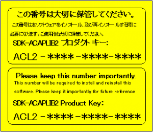
If the license key is not registered, you will see the pop up message “Registration is not done” every time.
To eliminate this message, it is required to register the product key.
(NOTE : If you are using this software for evaluation purpose, press OK on the popup window. You can use all funtionalities with valuation version.)
To register, find the AvdRegistTool from the Start menu.
Start menu – [AVALDATA] – [SDK-AcapLib+] – [Tool] – [Registration] – [AvdRegistTool]
※ You must run this program as administrator.
Select the product version to enter the product key and press OK button.
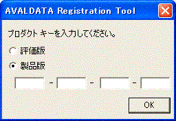
If the product key is not registered when the library is executed, a dialog box called Registration is not done is displayed.
It does not affect the operation, so for evaluation purposes, use OK as it is.
A separate runtime license is not required after the first purchase.
You can also use as it is if you have a license of SDK-AcapLib2, SDK-TransFlyer.
Following models are compatible with AcapLib+ Ver 1.8.1 or higher.
- APX-3800 / 3841 / 3842 (Opt-C:Link)
- APX-3502 / APX-3504 (Analog board)
- APX-3302 / APX-3323 / APX-3324A / APX-3326A (Camera Link)
- ASB-1302 / ASB-1323 series (Opt-C : Link / Camera Link)
※ Depending on the model of the ASB-1300 series, the types of SDKs installed in advance may vary.
Models with preinstalled SDK-AcapLib2 can also be used manually by installing SDK-AcapLib+.
- SDK-AcapLib + ASB-1302opt – ***, ASB-1302opt – *** ASB-1323opt – ***, ASB-1323opt – ***
- SDK-AcapLib2 ASB-1302 – *** ASB- 1302 – *** ASB-1323 – ***, ASB-1323 – ***
- Language : C++, C#
- Environment : Visual Studio 2005 and later
Other environments are not eligible for support.
It is supported in the following versions of Windows both Japanese and English edition.
- Windows 7 (32 / 64 bit)
- Windows 10 (32 / 64 bit)
※ Linux is not supported.
The memory is obtained 256MW(512MByte) * 2ch, and at least 1GByte +α capacity memory is required for operating OS, etc.
In Stream mode, it allows data to be stored on your PC during acquisition when at least two banks are granted.
In case the bank is set with only one, the following data cannot be acquired while the previous data is being stored.
Therefore, it is highly recommended to use at least two banks.
If you are using the trial version, you will see “Registration is not done” every time you run the program. In case user purchases the license already, please register the license at SDK registration tool. Once registration is done, pop-up will be disappeared.
If user does not have license key yet and under evaluation the board, pop up message keep apprears though, user can use every menu provided by SDK.
Please check if buffer is overflowed or not.
For more information about buffer overflow, please refer the software instructions.
- Evaluation tool(Windows only) is provided with SDK, and It helps API calls during programming so that API calls can be displayed such as function evaluation and acquisition.
- You can download it from link.
It can be used in various application area where it requires data acquisition such as medical devices, measurement device, inspection devices, telecommunication devices, and etc.
Our board is compatible with LabVIEW and LabVIEW’s VI library(※ LabVIEW 8.6 or higher) is provided with SDK.
Thru PCI-Express transferring data between APX-5000 and PC, data transfer rate is approximately 3.2GB/s.
Total time to be taken is adding HDD access time on above data bandwidth, and please check with hard disk manufacturer of accessing time to the certain device like HDD or SSD.
In the APX-5000 series, the PC’s GND and the analog GND are connected at one point.
It sets to 50Ω terminating.
It is sampled when the voltage changes to negative relative to 0V.
Because the input circuit is AC coupling, using sine wave is recommended. User can enter the signal such as LVTTL If not exceeding the maximum rating input
The board is equipped with 50Ω terminating resistance, so please make sure not to exceed the output drive current (maximum value).
Fixed frequency input cannot change the frequency of the external clock during the sampling period.
(If you change the frequency, PLL Lock will be turned off and you will not be able to perform accurate sampling.)
Variable frequency input can set and use external clock frequencies within specification during the sampling period.
(However, the variable frequency input cannot use PLL, so it must sample at the same frequency as the external clock.)
In case of being used as an external trigger, ± 2 clocks error per unit of sampling clock may occur.
Since each channel manage the sampling data through independent ADC, the synchronization errors between channels can occur, and it’s about ± 1 clock based on the sampling clock.
If you use sequence mode, you can set up to 16 conditions (tricker settings, capture start position settings, etc.).
This one capture condition is displayed in 1 Group unit. This can be captured continuously under different trigger conditions.
Stream mode and sequence mode
- Stream mode continues sampling until it stops.
- Sequence mode performs a specified size sampling after the trigger you set meets the condition. It then remains in standby mode until a trigger condition is established again.
For more information, refer to the user manual.
The filter, 200MHz-3dB, is equipped.
User can implement it with our FDK package. Further details, please contact your regional sales department.
Its level is LVTTL. (Value based on maximum specification)
DI:66MHz(CL=15pF)[Tpd=10ns(max)]
DO:50MHz(CL=50pF)[Tpd=13.5ns(max)]
(DO is the register output, which affects the speed of the PC.)
It is 50Ω division ± 350mV
Differential input is not supported.
If you want to do differential input, please prepare external differential buffer.
The driver can control up to 4 boards per series. If multiple boards are used on one PC, it is recommended that you check the specifications in advance, as each PCI Express slot may differ in performance.
You can also consult with regional sales contact before using it.
It may not function correctly when Windows’ power management mode is set to sleep mode or power saving mode.
We highly recommend to OFF such functions before using SDK.
- Up to 1Gbyte(512M Points) of memory is available per 1ch.
Evaluation tool is provided with SDK(Self Development Kit), and several sample sources are also included in SDK.
SDK is required for one time purchase per user registration.
This series board is equipped with SMA connector.
- Including 6 pin PCI Express power connector
- Air flow around the board
- No circuit causing magnetic flux in surrounding slots
- PCI Express Base Specification Rev 2.0a x8 or higher
For more information on each mode, refer to the user manual
- Single mode
- Normal mode
- Sequence mode
- Stream mode
Our board is compatible with LabVIEW and LabVIEW’s VI library(※ LabVIEW 8.6 or higher) is provided with SDK.
You can get a size of 2MB
The time is depending on the sampling period.
Sampling period = 10㎱ : 20.44㎳(=10㎱ x 2044KB)
Sampling period = 655.36㎲ : 1399s(=655360㎱ x 2044KB)
[APX-500 series – related to product usage] Does this board is equipped with anti-aliasing filters ?
Anti-aliasing filter is not equipped. In case of installing it, please install it as close as possible to the SMA connector.
[APX-500 series – related to product usage] Can I apply our-own algorithms within FPGA on the board?
It varies by product or specification, so please contact our sales department.
Its level is LVTTL.
DI:66MHz(CL=15pF)[Theoretical value: Tpd=10ns(max)]
DO:50MHz(CL=50pF)[Theoretical value: Tpd=13.5ns(max)]
(DO is the register output, which affects the speed of PC.)
LVTTL level (5V allowed).
Differential input is not supported.
This can be done by using an external trigger.
On-board clock has ±1 error.
To eliminate the error, enter an external clock at a low speed.
It can be input up to 20MHz@-3dB(representative value).
The driver can control up to 4 boards per series. If multiple boards are used on one PC, it is recommended that you check the specifications in advance, as each PCI Express slot may differ in performance.
You can also consult with regional sales contact before using it.
It may not function correctly when Windows’ power management mode is set to sleep mode or power saving mode.
We highly recommend to OFF such functions before using SDK.
Evaluation tool is provided with SDK(Self Development Kit), and several smaple sources are also included in SDK.
SDK is required for one time purchase per user registration.
This series board is equipped with SMA(F) connector.
The product does not include the cables.
If you have a question how to purchase the cable, please contact our sales department.
We recommend to use the PC meets following specifications.
- Full size PCI mountable
- Air flow near the board should be smooth
- No circuit causing magnetic flux in surrounding slots
- PCI Express Base Specification Rev 1.0a x4 implementable
When a Thread or a Process is on going, the other threads and processes need to be waited until current process is completed because access to shared memory of the board is always done exclusively.
You can read an data on the memory block that is being written, but the data is not coherent.
Use the door bell for data synchronization that the bell sender can notify to the bell receiver of data writing completion, then the receiver starts to read the data.
Yes, it is normal situation.
xxxxFinalize() is in the process of releasing internal resources, but it remains in the state of the hardware. It will be linked as soon as you restart the application.
The buffer pointer value and transfer size of the application that is transferred as an factor of the function might be causing the trouble.
Please verify that the buffer pointer and transfer size meet the conditions indicated in the user manual:
・Which is in alignment units
・Which is within range or not
When ERR LED turns to red while communication, please check if one of the followings is the case.
- In case the temperature surrounding the board exceeds the operating temperature indicated in the user manual.
- Disconection between the connector on board and the optical cable(Connect the cable to make a rattling sound.)
The following causes the ERR LED to turn red:
- Master node is overlapped
- Link state has changed to not established
- Retry processing by hardware is timed out
- PHY detects CRC error and framing error
There is no specific sequence require for node setup and user can freely setup the node by user’s preference.
However, in case the master node exists even if the node ID is overlaped, please check the link connection again before link to the nodes. Overlap node ID cannot be checked by the software, so communication does not work correctly.
Since by the master node’s existence or nonexistence per se can control the link state, it is recommended to configure the master node at the end. In this case, it is easier to connect because it only waits for the connection state of the application on the slave node. The same processing sequence can be performed each time by setting the master node to “external” right before the application ends.
It is highly recommended to OFF these functions to operate the system stable.
Sampled application for measuring speed is provided with the SDK.
It is including the source code with C or C#, and user can refer to it.
Please find the list of supported OS available to click here
※ If you wonder that OS not mentioned in list is compatible with GiGA board, please contact your regional seller.
GiGA driver can control up to 4 GiGA boards which supported by that driver in 1 PC, and It is also able to control the GiGA boards which having different transmission speeds and control disconnected links as well.
If you want to configure multiple connections in 1 PC, we recommend to consult in advance with your regional sales contact to prevent unstable operation might be caused from that every PCIE slot has different performance.
BER = 10 -¹², based on the specification of the SERDES · optical module.
You can check transmission speed per model this page. GO to the page
Optical cable is not included in product package.
If you want to purchase the cable together or want to know recommended cable specification, please contact your regional sales person.
Yes. you can use GiGA board even if your system does not have PCI Express slot.
AVALDATA proivdes GiGA board in 2 different types. One is called APX series supporting PCI Express, and the other is called AGM series which is controlled though FPGA.
If you want to use AGM series, please contact your regional sales person how to integrate this card into your system.
Each board has supported System BUS as shown below. Please refer to the fourth item from the left of the table below.
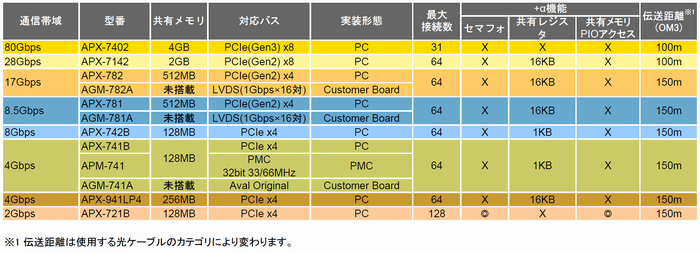
There are several models available for each communication speed or shared memory.
For product variation, please click here to move to page of GiGA board selection.
Yes. You can use any product in case that frame grabber is compatible with CameraLink standard.
First, please install SDK-AcapLib2, the software that corresponds to the CameraLink camera.
You can capture the images with AIPTool.
Detailed information regarding the sequence of capturing, such as how to install SDK-AcapLib2, or how to use AIPTool, can be found in the separate manual provided.
Please request to download the email address below.
The following software had already been tested successfully with our cameras.
■ Image processing software
- Cognex:VisionPro Version 8.2 SR1
- MVTec:Halcon 11.0·MVTec:Halcon 12.0
- National Instruments:Vision Assistant
- National Instruments:Vision Builder AI
■ Following SW will be tested soon.
- Matrox:MIL-Lite
- Stemmer:Common Vision Blox 11.0
- FAST:WIL Ver.3.0.x
It can be used for testing purposes, and we recommend to use this adapter only for testing purpose for stability.
※Please be noted depends on adapters’ quality camera cannot run at fast frame rate due to limited CPU load or lower data throughput.
It takes approx. 35 seconds for completing initialization after the camera is powered on.
Please be await until Power LED turns to green. (Status LED can be found at rear panel.)
We recommend to use CAT5e or higher shielded cable.
SWIR camera is equipped with InGaAs sensor which responds within near-infrared spectrum only.
Therefore, light source within visible ray does not work to this camera.
Please find the lighting emitting the light within spectrum the camera can respond.
Sensor’s temperature is one of important factors influencing on image quality.
Thermal noise as the sensor temperature rises, is especially noticeable in dark scene.
To prevent image quality deterirating from thermal noise, all of our cameras are equipped with Peltier cooling module that drops sensor’s temperature and it is great for reducing the camera noise.
User can update FW with their PC.
■ Camera Link
You can update it with terminal software such as TeraTerm.

■ Ethernet
You can update it with camera network setting tool,”TConfigurator”

It is not supported to supply power from PC to prevent the camera’s quality from deteriorating.
Please use DC12V(±1V), 1A for power adapter.
※The adapter is not provided as an accessory.
※GPIO signal is connected to the DC12V connector, and dedicated cable must be used.
User can save max. 2 different settings to non-volatile memory.
※When saving and loading the sets, memory number selection and command execution have to be done.
Camera provides Hot pixel, dead pixel/ Fixed pattern noise/ Poor sensitivity correction.
※ It cannot be corrected perfectly.
In general, InGaAs itself causes the pixel to defect, and the CMOS sensor generates noise.
■ Random noise
- Thermal noise
- Reset noise
- 1/f noise
■ Fixed pattern noise
- Shot noise
- Quantization noise * Photo-electic convert noise
- Sensitivity/Saturation noise
- Pixel defect(Hot pixel, Dead pixel)
To get an image, the camera should be exposed to the light and the sensor reads out after exposure. In this process, the time (exposure time + read out time) must be set less than the scan rate which is frame period.

Ex) In case of ABA-003IR (read-out time : 16,057㎲)
What if an user sets frame rate to 50fps(=frame period 20,000㎲) and exposure time to 10,000㎲
The sum of these time is is 26,057㎲(exposure 10,000㎲ + read-out 16,057㎲ ), and it is greater than frame period.
In this case, the camera corrects exposure time to 3,943㎲(20,000㎲ – 16,057㎲) automatically and runs.
Area scan camera takes 2D image at one exposure, and line scan camera captures one line only at one exposure. Therefore, it is required to be setup with a moving stage and an encoder to sync image. (Line scan camera requires several processes and the environment for the device working correctly to compose 2D image.)
Considering system cost basis, it is much cheaper to set the system with Ethernet.
(Because Ethernet type is not require for many devices such as frame grabber, separate communication cable)
and some functions can be varied per interface like max. frame rate or others. So, to select the interface type of the camera, the first action to do is to find out settings of testing environment, system budget, and etc., and select the model with the best fit for user’s application.
From 0.5m to 150m is available, and it varies depending optical cable you use.
(*8 Gbps, OM3 cable usage is the standard)
| Optical Module | OM1 | OM2 | OM3 | OM4 |
| 4.25Gbps | 70M | 150M | 150M | 150M |
| 8.5Gbps | 21M | 50M | 150M | 150M |
| 10.3125Gbps | – | – | 100M | 150M |
| 14.025Gbps | 15M | 35M | 100M | 100M |
If you install Ethernet Camera Control Software “SDK-transFlyer” of our company, both viewers will be installed. Based on the purpose of the use, pleases select the appropriate programs.

IR camera
This program allows you to control camera shooting, video display, and simple settings.
Camera settings can be operated with limited control (5 items) and intuitive GUI for easy operation
All functions provided by the camera (LUT, various calibration functions, etc.) are not available for this program

TSight
This is the software used mainly for developers.
All functions of the camera are available, but the difficulty for the operation is higher than IRcamera.
 ENG
ENG KOR
KOR CHN
CHN JPN
JPN